A 10 Watt miracle,
Some of you might be wondering 10 Watts?, my little brother's one battery
walkman produces more power.. Well in that case you'll probably don't know
the difference between a class AB and a class A amplifier. Class AB is
used in most off-the-shelf amplifiers. They provide a pretty good performance
at very reasonable efficiency, unfortunately they also provide several
forms off errors, like crossover errors, and these faults are very difficult
to suppress.
Therefore some fanatics prefer Class A. They don't care about its awfully
bad efficiency, but just want sheer quality. The Amp I build burns 60 Watts
at rest, and gives a max. output power of 10 Watts, that's a efficiency
worse than 20%!! (allrighty).
 |
 |
 |
The schematics I used for this End Amplifier (you'll need an additional pre-amplifier to control volume and stuff) came from an issue of the, unfortunnaltely deceased, dutch magazine Audio + Techniek (nr. 67, December 1998), this article was written by Rudy van Stratum. This magazine normally focuses on glass amp's but in #67 the 7 all-time best transistor amp's are discussed. Among them is 'my' JHL amp. It was a design from 1969 (say stone age) published in a magazine called Wireless World. It consists of only 4 transistors, which are all easy to get, and (very important for a student like me) very cheap. The work-horses in this circuit are the very well known, 2N3055's they cost me only fl 2.15 each ($ 1.00, 0.97 euro). The more expensive parts in the amp are (ain't they always) the cooling blocks (you need to cool away 60 Watts!!), the transformer and the capacity in the supply (can't have enough of those). For the complete schematics, see underhere. I have some photo's planned, but don't now on what term. I've also included a parts list and the spice files + models.
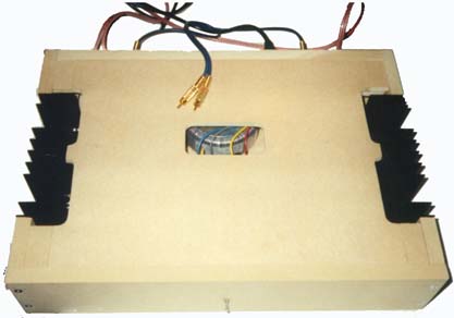
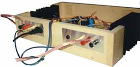
After I build the amp, with the two transistor mounted on an 1 °C/W cooling block, I discovered it was not going to work with the 1 Ampere rest current. So I screwed down the rest current to 0.5 Ampere, the amplifier produces less power this way, but at least it doesn't produce smoke. Unfortunately I discovered my error after I had mounted all the parts in a very nice housing. Fitting the amp with another cooling block would mean ruining the house so I keep it this way until I have time to build a new case with the proper cooling, say 0.5 °C/W. Many people have advised me to use forced cooling by way of an electric fan, but I think a fan doesn't belong in a Class A amp, it is to noisy, (and quite unreliable too). Another trick to lower power/heat consumption, is to lower supply voltage, the 40V from the schematic is quite high, nowadays I run it on 30 Volt.
Another problem I encountered after building the amp were the switch-on bloobs, somebody smart advised me to bridge the supply capacitor with small fast capacitors. This works quite good, the bloop has degraded to an acceptable level.
Capacitors can also be used to change the sound, by putting them in parralel to the output capacitor. This ouput capacitor itself must be of outstanding quality too, I use a Philips component, but I'm dutch. Some people advised me to put a ceramic capacitor next to the output elco, but I didn't like that, the high tones get the overhand, and the amp sounds very shrill. After some experimenting I use to polypropylene caps of 100n. My input capacitor is also polypropylene.
Schematic,

The numbers in this schematic represent the nodes in the PSPICE simulation, you can download it here. Note that the adjustable resistors aren't separately mentioned in the spice circuit file. If you don't have spice lib's with the required components you can download them here.
 |
The adjustable resistor R8 is used to set the voltage on point 7 at
50% off the supply voltage (here mentioned as 40 Volt, but that may be,
actually it better be, lower. 35 Volt is pretty nice (remember the higher
the supply voltage the more cooling should be used.)). Pot R4 is used to
adjust the rest current through the end transistors. It's pretty smart
to put them in maximum position before firing up for the first time. If
they are in minimum position the current might well exceed the 5 Ampere. My supply is build very
basic, transformator (two separate sec. winding, one for Left, one for
Right), followed by a
diode bridge (a 5 ampere type, slightly cooled) and (in my case) 24.700
uF of capacity (50-63V). But for the capacity the credo is; The more the
better. So I might upgrade this after I've won the lottery.
|
Remeber that this amp does not use any protection circuitry. If you short the ouput leads, you can through the amp away (well, at least the power transistors). If it get's too hot, nothing will prevent it from destroying itself. Be Aware!
I am very satisfied with this amplfier, it sounds better than most commercial designs for not very much money (caps, cooling and transformer take most of the budget)

Finally
If you have any questions or, even better, tips for me. you can email me at mtinholt@dds.nl. Remember that John Linsley hood has written several books on audio equipment, you'll probably find them at www.amazon.com.